Electrochemical test cells
Before you start your electrochemical measurements think about the experimental setup. You can immerse your three electrodes in the measuring solution and measure the current or the potential in a corrosion test. But, in this way you neglect the impact of the geometrical parameters, such as the distance between the reference and the working electrode or rather between the working and the counter electrode, on the measurement result. You do not reach comparability that way. You can do better! To reach comparable results, you need a cell design with defined geometrical parameters to control the distance between the electrodes each other and the size of the working and the counter electrode. You have to work with a comparable experimental setup – with the electrochemical test cell FlexCell.
Due to long-standing experience especially in the field of fuel cell, battery and corrosion tests we are able to construct an electrochemical cell which eliminate all known mistakes.
FlexCell
test cells for voltammetry and corrosion
FlexCell is the optimized electrochemical cell, voltammetry test cell, corrosion test cell for the electrochemistry with a three-electrode set-up. Working electrode and counter electrode are adjusted parallel. The reference electrode, mainly the mini hydrogen electrode Mini-HydroFlex, is located in a separate reservoir. It measures the potential via a drilled and thus fixed Haber-Luggin capillary which ends directly with a fixed distance to the working electrode.
Flexible regarding to the sample (e.g. metal sheet, foils, gas diffusion electrode) – but rigid where it really counts:
- Fixed and thus defined distance between the working and the counter electrode
- Fixed and thus defined distance between the working and the reference electrode
Planar electrodes, e.g. metal sheets, as well as gas diffusion electrodes (active area
3 cm²) can be installed as the working electrode. The working electrode and the integrated counter electrode (out of inert platinum) are adjusted parallel. This leads to parallel streamlines.
The reference electrode is in a separate reservoir so that the streamline flow is not interrupted. A Haber-Luggin-Capillary connects the reservoir and thus the reference electrode with the major electrolyte area. It ends directly with a fixed, defined distance to the working electrode. Therefore, the potential of the working electrode is always measured at the same point. The working electrode can be supplied with gases as necessary.
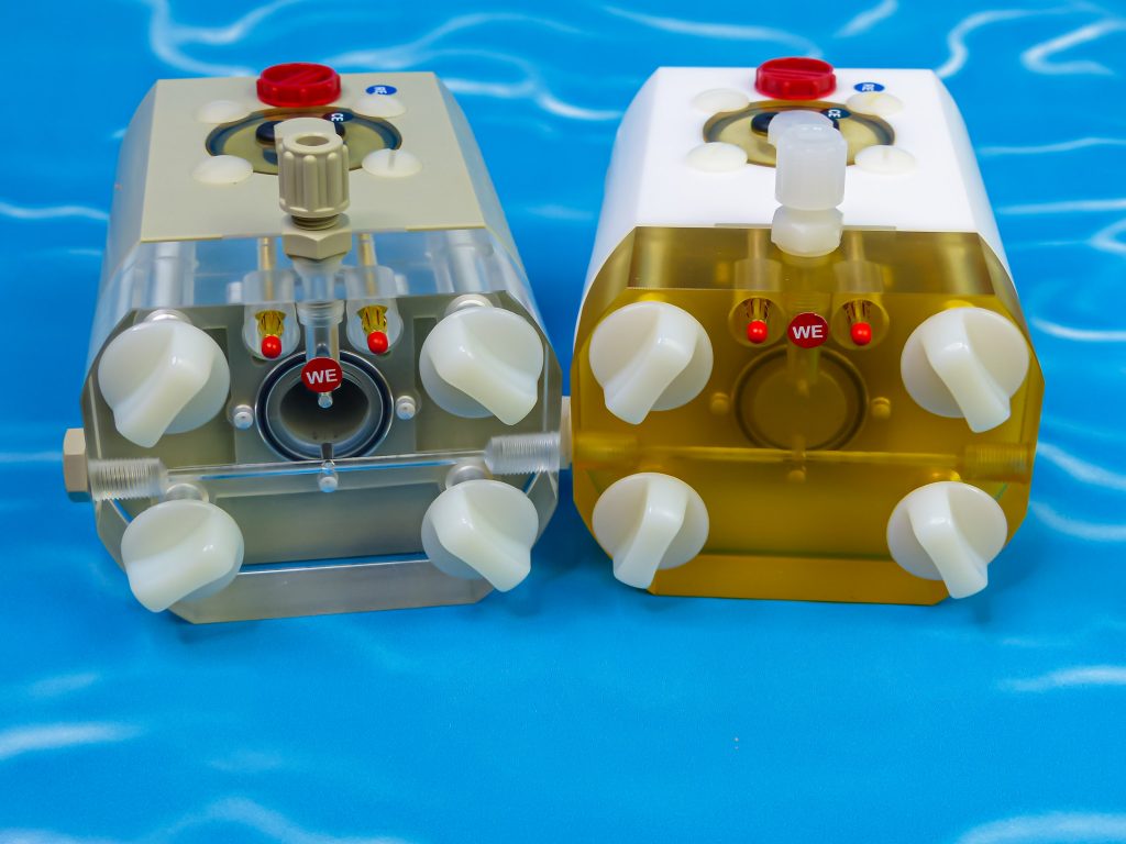
This voltammetry test cell and corrosion test cell is chemical resistant and indestructible since it is made of propylene (PP) or polytetrafluorethylene (PTFE).
Both variants can be used in a pH range of pH -6 to pH 16.
The electrolyte volume is only 30 ml.

By loading the video, you agree to YouTube's privacy policy.
Learn more
FlexCell – the electrochemical cell, voltammetry test cell, corrosion test cell for the electrochemistry with a three-electrode set-up
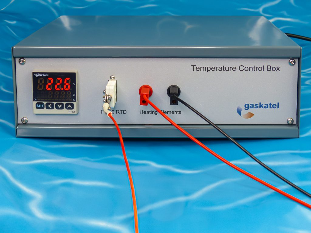
Temperature controller for testcell FlexCell
download manual FlexCell download manual temperature control boxMeasurements at higher temperatures, 80° C (PP variant) or 150° C (PTFE variant), are also possible. There are drillings on the back of the test cells in which appropriate heating elements can be inserted. The contact is made via 4 mm banana sockets. The temperature control takes place via a Pt100-probe. For temperature control, use the temperature control box from Gaskatel.
Manufactured of plastic
Test cell FlexCell is made of propylene (PP) or polytetrafluorethylene (PTFE). Both plastics are characterized by high chemical resistance. You can even measure in fluoride and highly alkaline media with the PTFE test cell. These electrochemical cells (test cells) are break-resistant and quasi indestructible. Due to the CNC-technology, a precise manufacturing of all relevant drillings and deepenings for seals is possible.
Three-electrode set-up
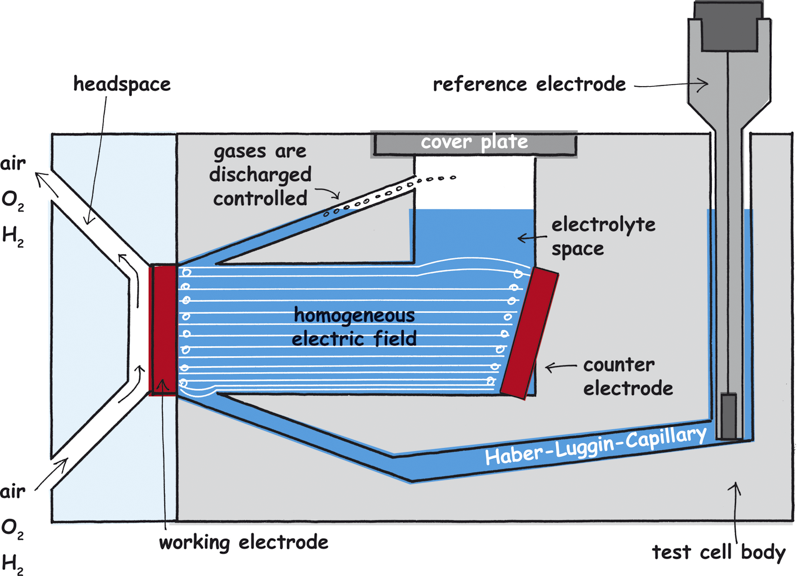
The three-electrode set-up is used during measurements in electrochemical cell with current flow. The working electrode is formed by the material which is to study. The current is measured via the counter electrode. Working and counter electrode should be adjusted parallel to each other. By means of the reference electrode the potential of the working electrode is measured. The reference electrode has to be located closely to the working electrode. That is reached by the Haber-Luggin-Capillary.
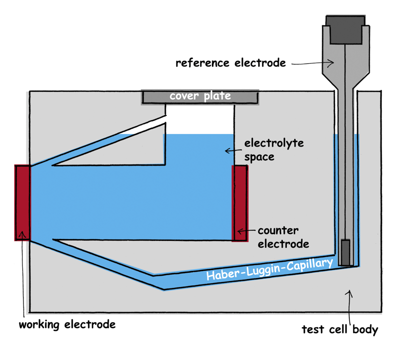
Three-electrode set-up in the electrochemical test cell with an integrated Haber-Luggin-Capillary which is shown schematically
Parallel field lines and equipotential surfaces
When current is flowing a streamlines field arises between the two electrodes whose course depends on the geometry of the electrodes to one another.
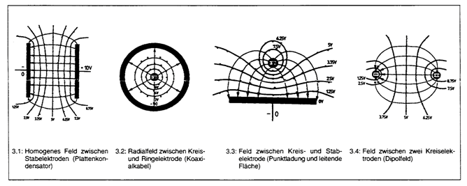
Electrical field line courses and their equipotential surfaces
The potentials which are to measure are only identical on the so-called equipotential surfaces (surfaces of the same potential which are vertical on the streamlines). If the field lines are not parallel the equipotential surfaces are not parallel, too. Thereby, the reference electrodes are often on different potential lines which leads to measuring errors. In addition, a second measuring error arises due to the voltage drop between the working and the reference electrode (IR-drop) which is caused by the electrolyte resistance and the distance between the working and the counter electrode.
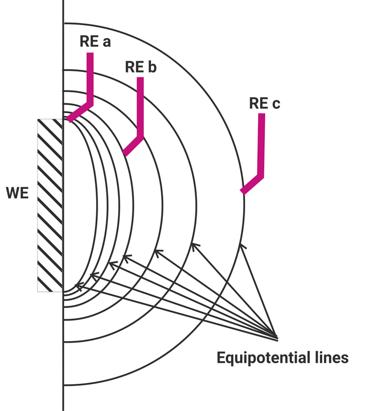
Equipotential lines at the working electrode and the position of the reference electrode

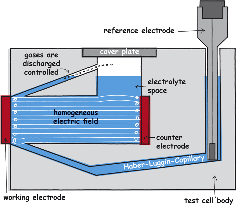
Homogeneous electrical field in the test cell FlexCell
So, the measurements are not comparable if the reference electrode is positioned differently from measurement to measurement. There are methods to identify the IR-drop before the measurement and save it as a correction factor during the measurement. But, be careful because
- These methods take place under current flow and can damage the sample irreversibly before the actual measurement
- The electrolyte’s conductivity depends on the temperature which changes during the measuring due to the current
- The electrolyte’s composition changes due to losses or dissolving components – thus the conductivity also changes
The IR-drop is a permanent changing value during the measurement, especially when you work with electrolytes of bad conductivity. To minimize the error and to run the potential measurement as replicable as possible, a homogeneous streamline field is needed as well as an immovable Haber-Luggin-Capillary. Only a tubular set-up with a working electrode as big as the counter electrode ensures a parallel field line course.
Importance of the Haber-Luggin-Capillary
The electrolytical contact between the working and the reference electrode is made by the Haber-Luggin-Capillary. It has to be positioned directly in front of the working electrode to minimize the voltage drop (IR-drop) across the electrolyte. The Haber-Luggin-Capillary must have a small diameter to not interrupt the field line course. The diameter must in turn be so big that the IR-drop is low. It has to be impervious to gas bubbles which block the capillary. Our Haber-Luggin-Capillary is filled with a solid electrolyte.
In this way, we avoid an accumulation of gas bubbles in the capillary which could lead to a dramatic increase of the resistance. Thereby, potentiostats can begin oscillating that ruins the measurements. What is more from the point of view of quality management is that all these factors remain stable with different half cells. The CNC-technology in plastic allows the precise positioning of the Haber-Luggin-Capillary to the working electrode. That ensures the comparability of the measurements among each other and between the test cell.
Gas bubbles at the working and counter electrode
In the electrochemical test cell FlexCell a small sewer ensures the discharge of the gas bubbles. They are controlled drained.
Where current flows through a liquid gas bubbles form either intentionally at the working electrode or as a result of side reactions at the counter electrode. Gas bubbles at the counter electrode can easily rise up to the top. At the working electrode there is the risk that many small bubbles accumulate to bigger bubbles and stick to the electrode.
There cannot be any electrolyte where the gas bubbles stick to the electrode. Gas bubbles can block the reaction surface and local elements can form.
Gas supply of gas diffusion electrodes
In the test cell FlexCell gas diffusion cells can be measured. They have to be supplied with the appropriate operating gas. The test cell FlexCell has a gas compartment to study gas diffusion electrodes which supplies the working electrode with gas without being flooded with the electrolyte.
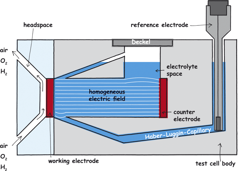
Gas diffusionselectrodes can be supplied with gases such as air, oxygen or hydrogen
Same surface of the electrodes
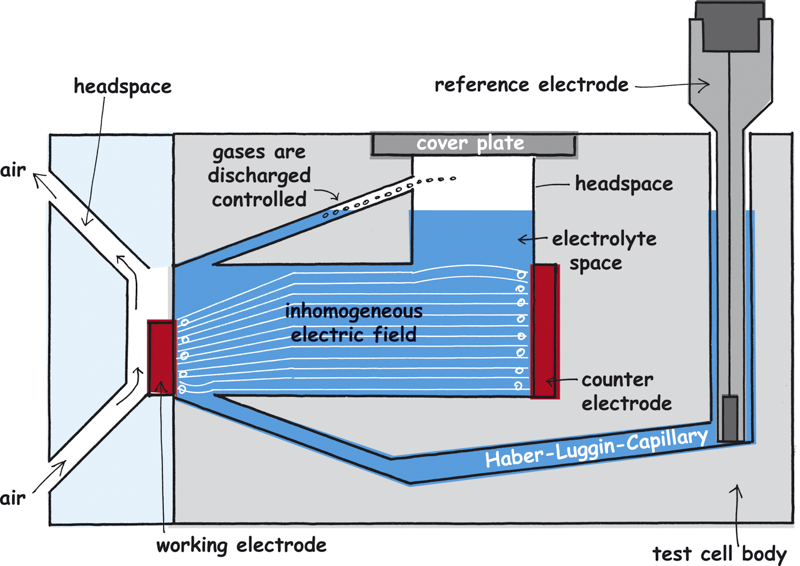
Inhomogeneous streamlines caused by a too small working electrode
In the electrochemical test cell FlexCell the parallel set-up of the working and counter electrode, their same size and the tubular orientation of the electrolyte chamber ensure a homogeneous electrical field between the working and the counter electrode.
So, pay attention that the active surface of the working electrode is as big as the counter electrode. If the working electrode is smaller than the counter electrode there is a compaction of the field lines at the working electrode which in turn causes a serious measuring error.
Parallel orientation of the working and the counter electrode
It is important that the electrodes are parallel to one another und are mounted vertical. A sloping counter electrode (as shown in the example) also leads to an inhomogeneous field and thus to measuring errors.
Inhomogeneous streamlines caused by the sloping counter electrode
Connection to the potentiostat
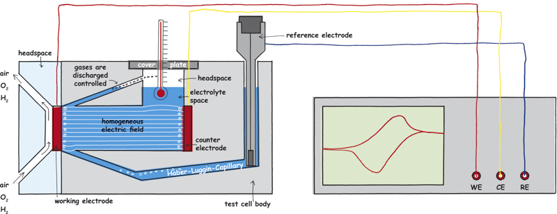
Test cell FlexCell and the connection to the potentiostat
It should be ensured that the electrodes are connected to the potentiostat via the correct inputs. They are usually labelled as WE for working electrode, CE for counter electrode and RE for reference electrode. Before connecting, please check if the test cables are corroded or damaged. Use the hydrogen electrode HydroFlex as the reference electrode to avoid contaminations. Furthermore, it is a reference electrode of low resistance.
Test cell FlexCell in a detailed cross section
1. Reference electrode: The cell shows a G1/4 thread. With the adapters the Mini-HydroFlex, the HydroFlex or a silver silver chloride electrode can be mounted tightly sealed.
2. Haber-Luggin-Capillary: Positioned directly in front of the working electrode and due to the use of a solid electrolyte impervious to gas bubbles which could block the capillary.
3. Tubular electrolyte chamber: Ensures an undisturbed field line course. To minimize water vapour losses the cell is closed by a lid.
4. Counter electrode: Platinum Iridium spiral, 0.3 mm strong. This wire is connected to the lid by a gold-plated banana socket.
5. Working electrode: Your sample is inserted between two seals. Therefore, the seals do not shift there are three PTFE pins. In order that the sample fits between these pins the sample has to be cut to the measures of 30×45 mm.
6. Contacting: Two gold-plated banana sockets 4mm. These press from the back on the working electrode. If the contact is not enough the banana socket can be retightened with a wrench. Observe the cleanliness of these plugs. Replace the plugs if the golden coat does not look well anymore.
7. Gas compartment: For the gas diffusion electrodes which further have to be supplied with gas. The gas compartment has two connections. The gas inlet is on top, the gas outlet is at the bottom. The gas compartment is made out of a Perspex plate so that the electrode can be observed.
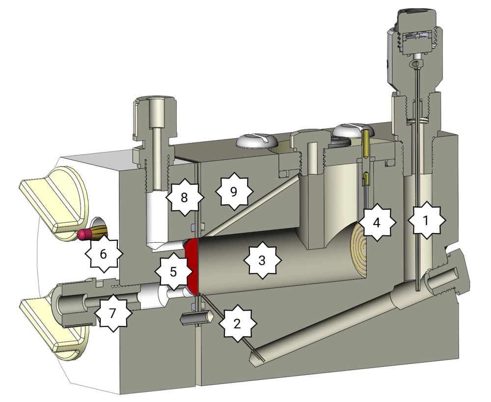
8. Seal: Flat seals and O-ring-seals. Flat seals are suitable for very noble materials, thin samples or gas diffusion electrodes. The O-ring-seals are suitable for ignoble materials such as steel or aluminium.
9. Gas bubbles outlet: Gas bubbles which arise at the working electrode can rise up at this point and thus do not disturb the measurement.
Protection to unwanted by-products
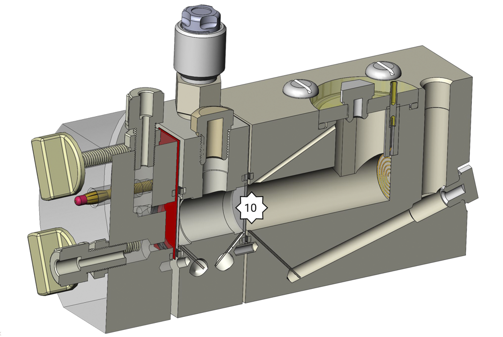
Reaction products of the counter electrode can get to the working electrode. Aggressive ions often arise at the counter electrode. According to the electrolyte peroxides, perchlorates or persulfates can arise. Even small amounts of these lead to corrosion at the working electrode. The test cell FlexCell can be equipped with an intermediate plate with a membrane to separate the working electrode from the counter electrode.
10. Membrane: Separates working electrode’s chamber from counter electrode’s chamber to protect the working electrode from unwanted by-products. To measure the potential of the working electrode the reference electrode has to be inserted in the middle cell.
With this set-up you can also measure membrane resistances – therefore, you will need two reference electrodes. One is in the analyte chamber and the other is in the actual drilling for the reference electrode.
With few handles and without tools gas diffusion electrodes can be mounted into our test cell FlexCell. Metal sheets are mounted in the same way but it is preferable to use appropriate O-rings instead of the silicone seals.
By loading the video, you agree to YouTube's privacy policy.
Learn more
With the additionally available analyte compartment for FlexCell, you can install a membrane to protect the working electrode from the reaction products of the counter electrode, for example.
If you have a bad conducting electrolyte, the potentiostat may start to oscillate due to these conductivity problems in the Haber-Luggin capillary.
In this case, the problems should be solved, if you use the analyte compartment with a much lower resistance Haber-Luggin capillary.
By loading the video, you agree to YouTube's privacy policy.
Learn more
If necessary, the counter electrode can be removed quickly, e.g. if it needs to be cleaned.
By loading the video, you agree to YouTube's privacy policy.
Learn more
During your measurements with electrochemical cells typical problems are caused by:
Corroded contacts and measuring cables
Check the measuring cables if there are any visual damages such as corrosion, cracks or sessile plugs. Replace the cables.
Reference electrode
Gas bubbles in the Haber-Luggin-Capillary or air bubbles in the inner electrolyte of the reference electrode can disturb the potential measurements. Diffusion voltages caused by the diaphragm of the reference electrode can cause measuring errors.
Electrolyte film
An electrolyte film between the reference electrode and the counter electrode can lead to a short.
Contaminations
Contaminations, degradation products, corrosion products can lead to incorrect measurements.
Battery status
An infirm battery of handheld multimeter lead to wrong voltages.
Potentiostat and filter
The potentiostat often reacts very delicate to electrolytes and/or samples with inadequate conductivity or gas bubbles in the Haber-Luggin-Capillary. It begins to oscillate. You can find more helpful information here What-can-cause-my-experiment-to-be-noisy.
Software
Pay attention to the correct input of the signs of your measurement parameters in the software. Bugs in the software are also possible.

 Deutsch